Sunday, October 31, 2010

Installed Brake Reservoirs & Bleed Brake Lines – 5 Hours

Those who have been following this blog for some time will remember that back in March I mentioned the multiple brake reservoir location options. At that time I decided to wait until the engine was installed so that I could determine a location which would provide accessibility and keep the transfer hoses away from direct heat.

The final decision was to mount the reservoirs centrally on the firewall, on checking the height of the master cylinders I was surprised of how low I was able to mount the cylinders and still keep the reservoir bodies the highest point of the system. (Replenishment brake fluid is gravity fed into the system)

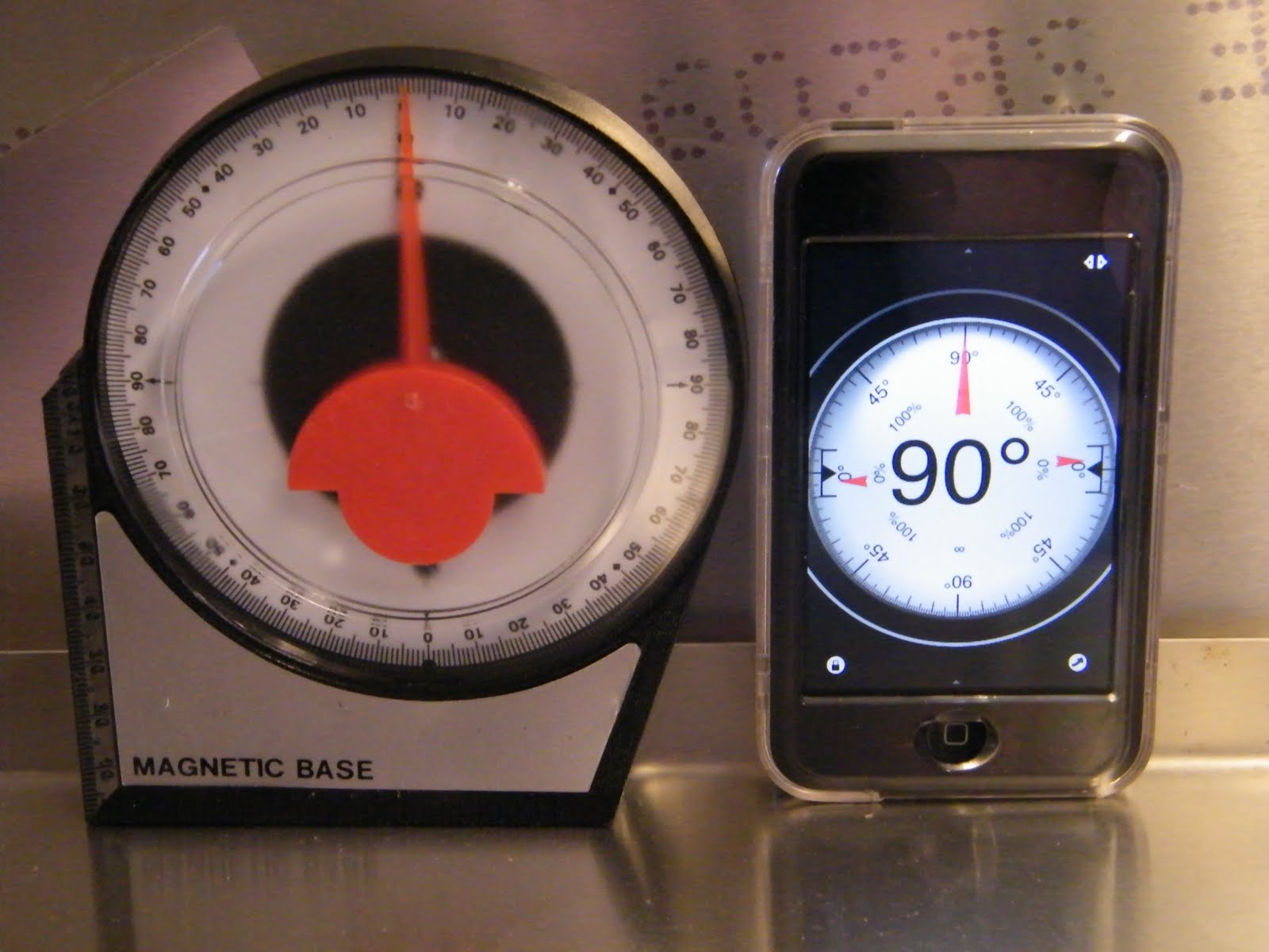
A hole saw opened up the inner driver foot box and 1” grommets were used to protect the hose from rubbing. The banjo fittings provide a simple 90 degree joint for the hose.

Only 2 small leaks were found in the system, both being at the “T” joints (3 connections) which divert brake fluid to the driver and passenger side calipers. These were tightened up and the brake system bled of air.

Remember always start at the caliper furthest from the master cylinder working towards the nearest, in this case the order is, rear passenger caliper, rear driver side caliper, front passenger caliper, front driver side caliper.

DOT5 synthetic brake fluid was used, although there are those who scorn this type of fluid, the fact that it does not function as paint stripper if spilled, easily out ways any slight down side.

Monday, October 25, 2010

Odds & Ends – 5 Hours

Time fly’s when you are having fun, or so it would appear having spent most of the day in the garage with little to show for the effort, however there are point’s of note:

1. The 4 drive shaft bolts tightened to a torque setting of 83 ft lbs, this being the value directly from the Ford Mustang factory manual. This did however require a trip to Lowes to purchase a 12mm 12 point 3/8” drive long reach socket. Having a collection of 12mm 12 point ½” drive sockets the diameter of these sockets are too large to clear the universal joint

2. Thinking ahead, knowing that once the radiator is finally mounted it will be difficult to drill holes in the X member, and after checking a number of possible locations, decided to mount the two tone horns on the front of the X member. This location is personal choice.


3. Installed the clutch cable. At build school the instructors stated that the standard cable supplied in the kit requires herculean strength to operate the clutch, these comments are often iterated on the forum. I am pleased to confirm, neither sources were exaggerated. This will be replaced with an original Ford clutch cable which supposedly rectifies the situation. (Will update post at a later date)

A convenient bolt hole on the front of the cylinder head was the ideal location to mount the clutch cable bracket which keeps the cable away from the exhaust headers.

Sunday, October 10, 2010

Dashboard – 3 Hours

The dashboard layout was completed today and test fit to determine functionality before beginning to run the wiring. Having reviewed a number of original dashboard layouts, the final chosen layout is as traditional as function would allow.

From left to right: tachometer, left turn indicator, main beam, right turn indicator, speedometer.

Top row: Water temperature, oil pressure, voltage.

Middle row: Wiper switch, fuel gauge, clock, main beam.

Bottom row: Horn, ignition, turn switch, lights, hazard, and fan switch

Still undetermined on installing a glove box, due to the limited area behind the dash once the EFI computer is installed.

Installed oil pressure sensor on the engine and ran cabling back to the dash.

Header and Exhaust – 3 Hours

Installed driver’s side header and exhaust, the passenger side header requires a CO2 bund to be welded in place before this is installed. After checking the EFI wiring harness and the fact that the passenger foot box is smaller the decision became easy to select the passenger side header as the location of the CO2 sensor. The headers are manufactured by BBK.


Many Cobra owners complain that header bolts come loose and even fall out, determined that this would not happen this installation is using Stage 8 locking fasteners, basically a grade 8 bolt uses a retainer which slips over the head and is held in place with a snap ring.

With the header installed the exhaust pipe was bolted in place, although the exhaust pipe is self supporting the vibration hanger still requires installation.

Again many Factory Five owners have complained that the exhaust pipes don’t mount parallel to the ground or run parallel to the chassis, after installation simple checks found this not to be the case with the driver’s side exhaust pipe, being zero degrees to the ground and parallel with the 4” main chassis tube.

Here’s hoping the same can be said when the passenger exhaust pipe is installed.

The first of 2 grounding straps was also installed prior to installing the passenger side header, the engine mount has a pre drilled hold to mount the strap to the frame, prior to installation the powder coating and engine block paint was removed with a Dremel to provide good continuity, once attached the area was then coated with dielectric grease to stop corrosion.

Saturday, October 9, 2010

Coolant and Fuel System – 2 Hours

Many builders complain that the corrugated coolant hoses are difficult to seal on the short run from the coolant pump to the billet filler. In addition to this needing to be a 90 degree bend, the diameter of the water pump outlet is different to the billet filler.

As the filler should also be the highest point in the cooling system I decided to purchase the Breeze Automotive 1.5” to 1.25” 90 degree elbow (part #70619).

Since build school I have never liked the model plastic coolant expansion tank supplied in the kit, beside it looking cheap (it’s actually from the BMW), it looks to modern. Factory Five have updated this in the new Mk4 kit, this being a stainless steel vintage looking unit (part #15030). This unit mounts on the F panel.


All fuel injection systems require a fuel regulator to main the correct fuel pressure for the injectors, this is placed in the return fuel line, although a pressure gauge is not necessary, it is the easiest way to set the regulated pressure.

As the fuel lines run along the passenger side 4” chassis tube the fuel regulator was mounted on the firewall next to the passenger foot box, the vacuum line was then run to the throttle body.

Other jobs completed today included adding a 2nd temperature sensor, the reason I have two is that each is dedicated to either the temperature gauge or the EFI computer. The main EFI wiring harness was connected to all the injectors, and sensors in the throttle body and inlet manifold.

Sunday, October 3, 2010

Drive Shaft Installation & Pinion Angle – 2 Hours

Completed drive train installation and alignment, basically this consisted of manufacturing a ¾” spacer to go between the transmission mount and the transmission support. This spacer is only required when installing either a TKO 500 or 600 transmission. The use of the spacer results in the transmission output to be parallel with the ground.

All engine mounting hardware was tightened using the following torque settings:

Engine mount to engine block 50 ft.lb’s
Engine mount to frame 90 ft.lb’s
Transmission mount to transmission support 55 ft.lb’s

Before installing the drive shaft, the pinion angle requires setting. The ideal pinion angle is when the angle of an imaginary center line from the transmission output and an imaginary center line from the differential input are parallel when under load. This angle can be zero, positive or a negative angle, but must be parallel for the universal joints to function correct. An incorrect pinion angle induces premature wear and “knocking” under load.

See pinion angle example (this assumes a 1 degree offset).

For the angles to be correct a differential offset angle needs to be accounted for when setting the alignment to compensate for rotational twist which occurs in the differential under acceleration. Basically the input flange of the transmission kicks upwards under load as the transmission tries to rotate around the axle. With a 3 link suspension 1.5 to 2 degrees is recommended.

As complicated as it sounds setting a pinion angle is simple, first you will need an angle finder, these can be purchased from any hardware store, of if you have an iPhone or iPod, down load any one of the applications. Make sure the vehicle is on the ground with suspension under load.

Measure the angle of the transmission output, the easiest way is to place the angle finder on the gasket, in my case this was 0 degrees, next set the differential input adjusting for the offset, in my case -2 degrees (differential input flange pointing towards the ground), the angle is measure from the flange face and adjusted by lengthening or shortening the upper link.

Once set the drive shaft was slid into the transmission and bolted to the differential flange using 4 bolts. Make sure there is no binding by rotating the assembly.