Saturday, October 9, 2010

Coolant and Fuel System – 2 Hours

Many builders complain that the corrugated coolant hoses are difficult to seal on the short run from the coolant pump to the billet filler. In addition to this needing to be a 90 degree bend, the diameter of the water pump outlet is different to the billet filler.

As the filler should also be the highest point in the cooling system I decided to purchase the Breeze Automotive 1.5” to 1.25” 90 degree elbow (part #70619).

Since build school I have never liked the model plastic coolant expansion tank supplied in the kit, beside it looking cheap (it’s actually from the BMW), it looks to modern. Factory Five have updated this in the new Mk4 kit, this being a stainless steel vintage looking unit (part #15030). This unit mounts on the F panel.
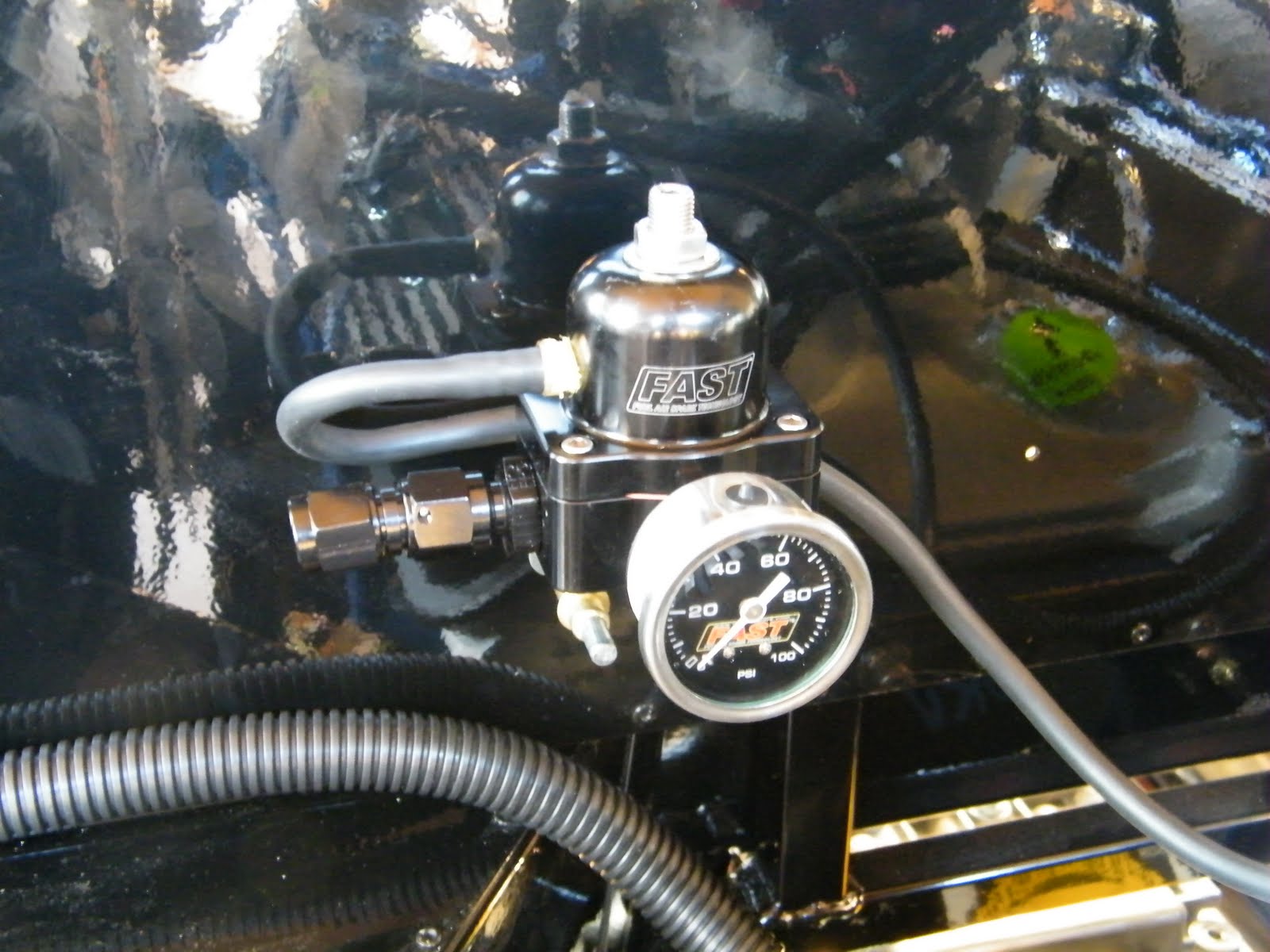


All fuel injection systems require a fuel regulator to main the correct fuel pressure for the injectors, this is placed in the return fuel line, although a pressure gauge is not necessary, it is the easiest way to set the regulated pressure.

As the fuel lines run along the passenger side 4” chassis tube the fuel regulator was mounted on the firewall next to the passenger foot box, the vacuum line was then run to the throttle body.

Other jobs completed today included adding a 2nd temperature sensor, the reason I have two is that each is dedicated to either the temperature gauge or the EFI computer. The main EFI wiring harness was connected to all the injectors, and sensors in the throttle body and inlet manifold.

Sunday, October 3, 2010

Drive Shaft Installation & Pinion Angle – 2 Hours

Completed drive train installation and alignment, basically this consisted of manufacturing a ¾” spacer to go between the transmission mount and the transmission support. This spacer is only required when installing either a TKO 500 or 600 transmission. The use of the spacer results in the transmission output to be parallel with the ground.

All engine mounting hardware was tightened using the following torque settings:

Engine mount to engine block 50 ft.lb’s
Engine mount to frame 90 ft.lb’s
Transmission mount to transmission support 55 ft.lb’s

Before installing the drive shaft, the pinion angle requires setting. The ideal pinion angle is when the angle of an imaginary center line from the transmission output and an imaginary center line from the differential input are parallel when under load. This angle can be zero, positive or a negative angle, but must be parallel for the universal joints to function correct. An incorrect pinion angle induces premature wear and “knocking” under load.

See pinion angle example (this assumes a 1 degree offset).

For the angles to be correct a differential offset angle needs to be accounted for when setting the alignment to compensate for rotational twist which occurs in the differential under acceleration. Basically the input flange of the transmission kicks upwards under load as the transmission tries to rotate around the axle. With a 3 link suspension 1.5 to 2 degrees is recommended.

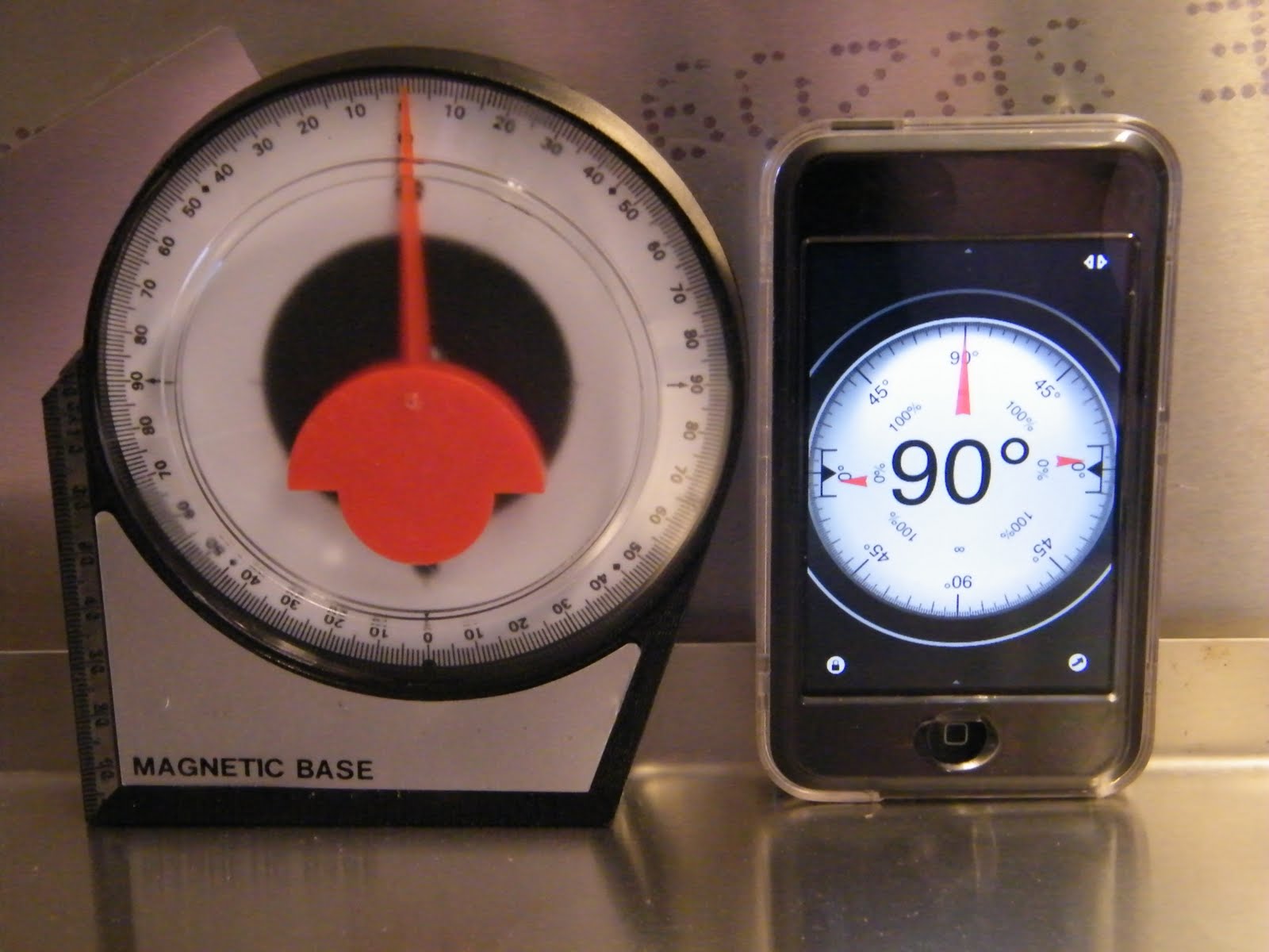
As complicated as it sounds setting a pinion angle is simple, first you will need an angle finder, these can be purchased from any hardware store, of if you have an iPhone or iPod, down load any one of the applications. Make sure the vehicle is on the ground with suspension under load.

Measure the angle of the transmission output, the easiest way is to place the angle finder on the gasket, in my case this was 0 degrees, next set the differential input adjusting for the offset, in my case -2 degrees (differential input flange pointing towards the ground), the angle is measure from the flange face and adjusted by lengthening or shortening the upper link.

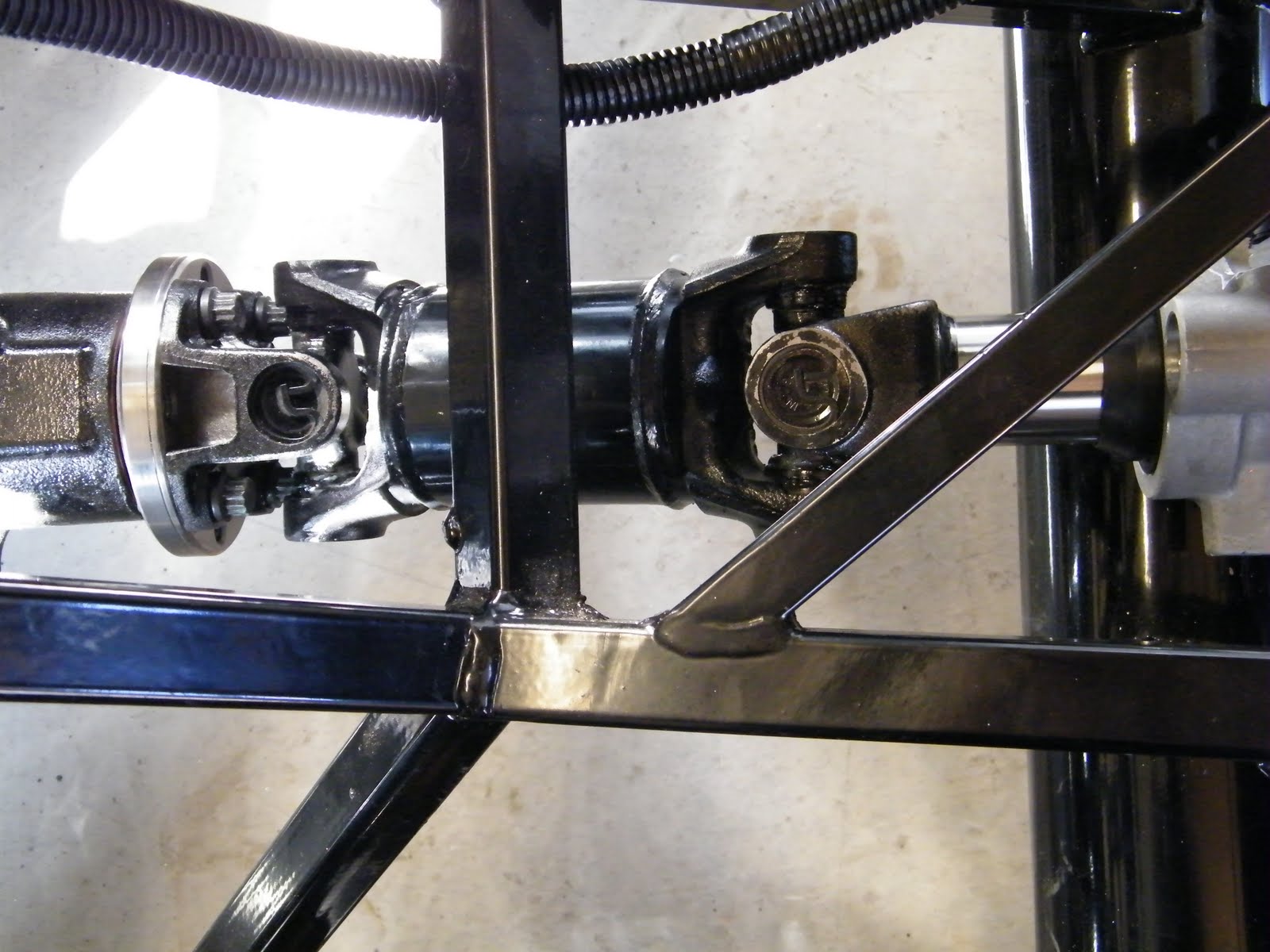
Once set the drive shaft was slid into the transmission and bolted to the differential flange using 4 bolts. Make sure there is no binding by rotating the assembly.

Monday, September 6, 2010

Engine Installation – 2 Hours

Today was a great day as the 2nd build milestone was completed with the installation of the engine and transmission. This keeps the build on schedule for a first engine start around Thanks Giving.


Tips and general information:

1. Use a 2 ton engine leveler, the ¾ ton leveler used although within the weight limit has limited span and chain length which meant that the EFI injection body needed removing.

2. Wrap and protect every area you think you may scratch or accidentally swing into. In the picture you can see bubble wrap around the lifting chain to protect the valve covers and inlet manifold, bubble wrap on the hydraulic cylinder as the steep transmission angle required results in the pulley’s hitting the ram. Radiator mounting bar and 4” cross tube all benefit from protection.

3. Jacking the rear of the car higher than the front reduces the angle required to swing in the transmission.

4. Use of a ratchet strap on the transmission helps jacking the complete assemble back towards the rear and aligning the engine mounts.

5. The large plate of aluminum under the transmission mount will be machined to form a ¾” spacer as required for a Tremec TKO.

6. Slow and steady, it’s not a race.

Saturday, September 4, 2010

Installed Transmission – 1 Hour


Part one of this weekend’s engine and drive train installation was to connect the transmission to the engine, you will see from the picture that the easiest method is to use a transmission jack as this makes alignment relatively simple. The transmission if aligned correctly should just slide in place. It took me 3 attempts because the input shaft requires rotating to align with the spline on the clutch.

Bolts should not be used to jack the transmission in place, the easiest method for aligning the spline’s is to place the transmission in gear and rotate the drive shaft, wiggling the clutch yoke also helps center the input shaft.

The Quick Time bell housing came with two sleeves which accurately align and support the nose of the transmission into the bell housing. Check that the correct one is being used and make sure this is inserted before assembling. Bolts were tightened to 50 foot pound of torque and marked with torque lock. Medium thread lock was used on the four bolts.

Tremec TKO 600 FYI’s

Finished the transmission off during the week, there are a couple of points not mentioned in the previous discussion regarding Tremec TKO 600 transmissions which are of note:

1. The large rubber bung in the tail shaft needs to be removed (do not throw away), the best way to do this is by using a pair of needle nose pliers gentle sliding these inside of the outer seal at 12 o’clock, 4 and 8 o’clock gently working the bung out (12 o’clock marks can be seem in the picture).

This should be kept as this seals the tail nose if the driveshaft is removed and will stop transmission oil from spilling if the transmission needs pulling at a later date.

2. If the electronic speed sensor is to be used then the rubber plug on the driver’s side where the mechanical speed sensor would be mounted needs replacing with a cap fitted with an o ring and held in place by a ¼” bolt.

3. The holes on the gear leaver needed drilling out to match the shifter arm.

Thursday, September 2, 2010

Started Dash – 2 Hours

After procrastinating since December on the final dash layout, today was the day to take the plunge.

From left to right: Tachometer (not installed), left turn signal, main beam (blue), right turn signal, speedometer, wiper switch, horn button and, ignition.

Tip: The turn and main beam lights are a friction fit, over time I have found these to work loose, the best way to fix this is to slip a rubber grommet over the fitting from behind during final assembly. This forms a simple rubber clip.

Sunday, August 29, 2010

Transmission Selection & Surgery – 2 Hours

After an 8 week break, due partly because of the excessive hot weather (7th hottest on record here in North Texas), but mainly because of work commitments in Europe, California and New York, it was with excitement that I cranked up the AC in the garage today.

There are many reasons I chose the Tremec TKO 600 (TCET 4617) over the standard T-5, and I thought I would re-visit these:

1. The primary reason was that with 275/40 R17 tires and a 3.31 differential, the engine would be laboring around 1900 RPM in 5th gear at 70 MPH, with a T-5 or TKO 500 (both have a 0.68 5th gear ratio). The TKO 600 offers a choice of a 0.82 or 0.64 final gear ratio. Choosing the 0.82 option results in a 70MPH cruising RPM of 2400, you may ask what difference does this make. (Please feel free to download the following calculator)


After driving in a number of cars recently many owners complained of having to drop into 4th gear to overtake at around 70MPH as the engine was not yet at the sweat spot, hopefully the transmission selected will overcome this.

There is a down side; the car will be a little thirstier on gas, and the top end speed will be reduced to around 150MPH, but as I don’t live near a German autobahn it’s unlikely this car will ever get a chance to prove itself.

2. Standard on all TKO transmissions is a choice of manual or electronic speed sensors, neutral safety circuit and a reverse gear sensor.

3. Although the TKO is over specified for the torque this engine will produce, the heaver drive train will be less susceptible to failure and wear with the aggressive driving the car will see.

4. Another available option is a mid-shift, although this is not planned, once I start driving the car and if I don’t like the shift location I do have the option to change.

This week I collected my transmission from Standard Transmission and Gear in Fort Worth (See web link), this is a great company and the deal they made was outstanding, strongly recommended. An issue with all TKO transmissions is that they require surgery before fitting in the Cobra.

The upper picture shows the unmodified rear of the transmission, the alternative rear transmission mounts need removing as these will interfere with the 4” round cross chassis member.


Second picture shows the modified transmission, this was achieved with a steady hand and a Sawzall, it took a couple of blades to complete the surgery both 14 and 18 tpi metal blades seem to perform the best.


Lastly transmission mount (last picture) was bolted to the transmission, remember to use the second mounting plate provided as this is actually a spacer and is not an either or option.

With luck and a fair wind I am hoping to bolt up the transmission during the week and drop the complete engine transmission and drive train in over the Labor Day weekend.

Sunday, July 4, 2010

Test Fit & Install Radiator, Shroud, and Fan – 4 Hours

Although the shroud and fan had been test fit and assembled, this assembly required attaching to the radiator, and the radiator mounted to the frame.

What was not anticipated was that the shroud required modifying to clear the radiator inlet pipe (see picture).

The shroud and fan are bolted to the radiator in four places with ¼” stainless bolts, the Factory Five frame has mounting lugs pre-welded, but require drilling.

Note: the radiator needs offsetting approximately 5/8” from center to easy the routing of the lower radiator outlet pipe. The three aluminum front nose panels reflect this offset and are not cut symmetrically.

As the radiator flange already has holes and slots pre-cut I decided to use the slots as this would allow some left to right adjustment of the radiator assembly during final assembly.


Factory Five relies on zip tie’s to hold the bottom of the radiator in position until the body is fitted, the aluminum panels mentioned above are then screwed and riveted into place to support the radiator. Not being keen on this idea, the Breeze “radiator chin strap” was installed.

The Breeze strap is simple to install but effective, as it easily allows the radiator to be installed at the 51 degrees from horizontal suggested.


All the above will be removed for engine installation, the shroud will be powder coated black, and strips of rubber will used between the shroud / radiator and the radiator / frame to absorb vibration, and allow some movement following expansion contraction of the radiator through various heat cycles.

Friday, July 2, 2010

Engine Porn – Sit back, Click, Watch & Listen


Today was as exciting as when the car arrived, yes you guessed, the engine delivered. The above video speaks for itself.

Part 2 of the build will now commence, engine and transmission installation, followed by the proverbial first start, if everything goes to plan this will be completed by Thanks Giving based on current work and travel commitments.

Monday, June 28, 2010

June Update - Milestone

It’s been nearly a month since my last post, a combination of work commitments and the early Texas summer meant that working in the garage became a challenge. As luck would have it the Engine Factory were delayed in completing the engine due to a national shortage of FAST EFI systems.

Today however was a milestone day, the Engine Factory ran the engine for 45 minutes without problems and the unit will be shipping tomorrow.


As to the Texas heat, this has been cracked with the purchase of a Danby 11,000 BTU portable air conditioning unit, roll on next weekend when work recommences in earnest over the long weekend.