Friday, November 26, 2010
First Engine Crank – 1 Hour
The original plan was to start the engine at Thanks Giving, unfortunately work has got in the way, really cannot complain, after all its work that pays for this car.
With the engine and dash wiring complete it was time to crank the engine over, first the clutch neutral tested for functionality and the area around the engine bay was checked for loose wires and other debris. As you can see from the video, the test went to plan.
The new engine start date is December 23rd, a fitting date as this will be 1 year since the car was delivered. This leaves plenty of time to mount the FAST EFI computer, hook up the fuel line, and add a charcoal filter.
Please enjoy the video, it made my Thanks Giving.

Dashboard Wiring – 5 Hours
 Don’t you just wish you had listened back then in college! It’s a little over 30 years since I attended electrical classes and the grey matter was tired then, or maybe just hung over. Anyway completed the dashboard wiring and installed the dash back in the car.
 Decided to stick with the Ron Francis dash wiring loom although did use a terminal block to simplify the wiring for the gauges, horn, and dashboard turn and main beam lights.
Tried to stick with 3 main cable runs, the upper cable run consists of the gauge feed and illumination pigtails, the cable run below the 2 lower gauges is for the horn, turn and main beam dash lights, this left room for the dash harness to run at the bottom of the dashboard.
 The light grey cables running off to the right are permanent gauge calibration and setting feed wires which are terminated at a panel which can better be seen at the bottom of the installed dash board picture. This panel will be mounted to the right of the fuse panel to allow easy access to re-set the trip, clock and calibrate the speed and fuel gauges.
 Once the dash was mounted back in the car, the fan and ignition were connected back up, as were all the gauge sender units. So far everything remains plug and play for easy installation and removal of the dash.
Sunday, November 21, 2010
It’s the small stuff that takes the time – 10 Hours
 Having spent most of the weekend in the garage, it’s not until you add up all that was achieved that you realize were the time goes.
With the panels back from the powder coater the dash filler was permanently installed, along with the fuse panel support and the passenger foot box filler pieces.
 Switching to wiring, the dash harness ground was drilled the powder coating removed before installing the lug and coating the assembly with dielectric grease, both to maximize the grounding conductivity but more importantly inhibiting rust.
The inertia switch was mounted to the left of the filler panel; beading was run around the dash filler to stop cable fraying.
 Clutch neutral wires were extended to reach the neutral switch at the rear of the transmission; the speed sensor plug was also spliced into the wiring loom. The brake switch connection was also made.
Moving to the engine bay the O2 sensor connector was mounted to the chassis, the positive battery cable was run to the disconnect switch. The one wire alternator cable was also run to the same side of the disconnect switch via a mega fuse.
 FAST EFI manual instructs running the positive and negative cables directly to the battery, thus terminal connections were made and the two wires installed in cable loom.
You may have noticed that all the wiring is specific to first engine start, over the next few days all engine wire will be completed (coil, starter), along with dash gauges, and ignition switch. Current plan is to at least crank the engine at Thanks Giving, with first engine start set for December 23rd, one year since the kit first arrived!

Saturday, November 13, 2010
Final Installation of Radiator – 4 Hours
 Also this week, the 2nd batch of panels was powder coated, including the radiator shroud. This meant that the radiator could be permanently installed and the coolant hoses, cut, fitted, and bent to shape.
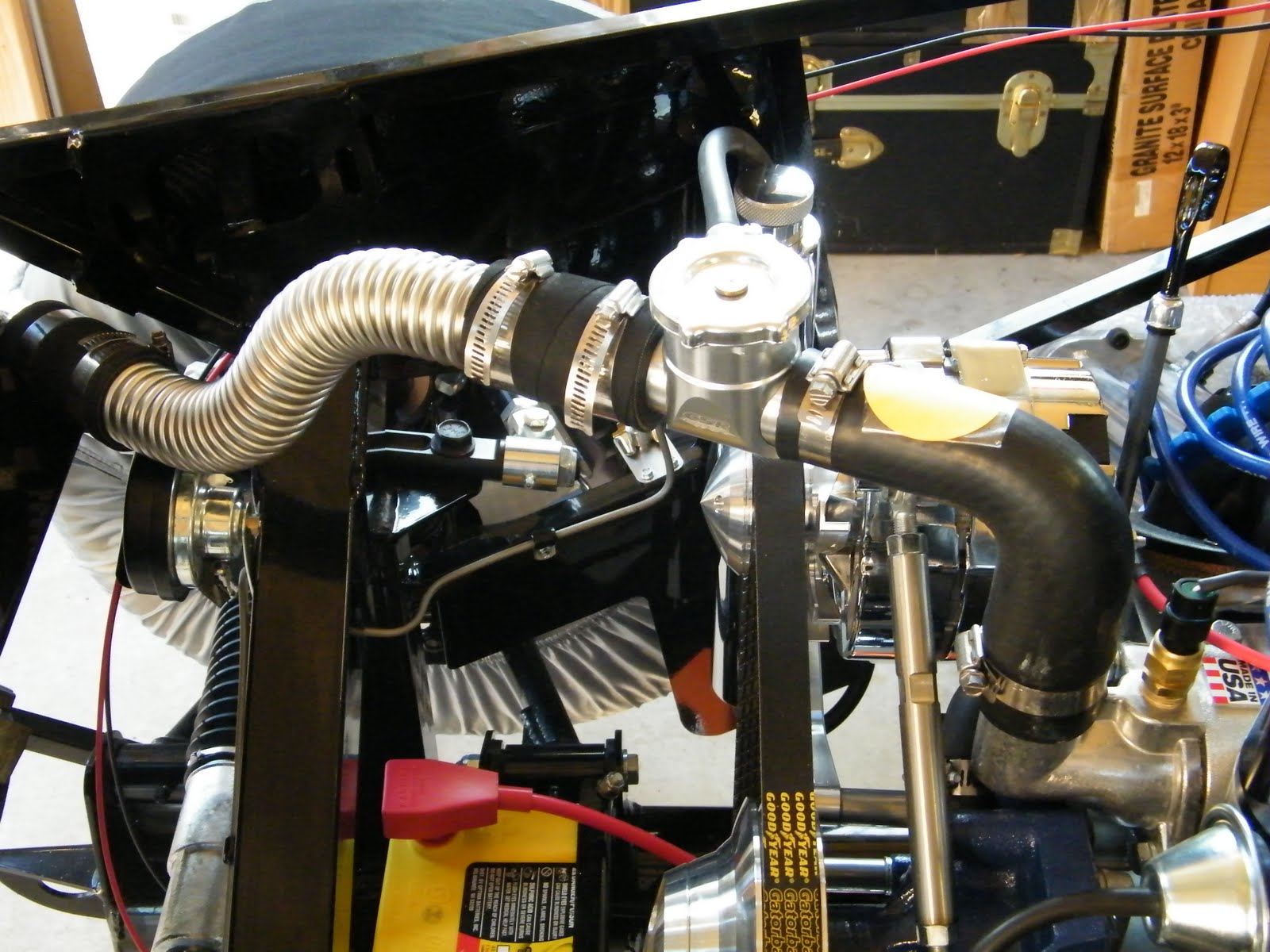 Ideally the radiator mount should account for vibration and not be a sold connection to the frame as this can lead to premature failure. To account for this the fan was mounted to the shroud using rubber washers, a 1/8” thick by ¾” wide rubber strip was used between the shroud flange and the radiator, the same rubber strip was used between the radiator and the fame.
 The Breeze lower radiator support uses rubber hose to provide a vibration mound at the base of the radiator. As per Breeze instructions the radiator angle was set at 51 degrees to the horizontal.
Factory Five provide a length of corrugated stainless steel hose which requires cutting to length, and formed to fit. The upper hose needed bending into a simple S shape to accommodate the vertical displacement between the radiator and the billet coolant filler.
 Routing of the lower hose is more involved, first clearing the chassis and then running the hose under the X member and over the 4” round chassis cross member before connecting to the engine. As this is a long run and a customer cushion mount will be manufactured to connect this hose to the underside of the X member.
 TIP of the week: Many complain that the corrugated hose does not seal with the rubber joint, the hose should go into the rubber joint about 1 ½” the hose clamp needs to seal on the outer corrugation, by measuring the pitch the distance between 3 serrations is ¾” using this the hose clamp can be positioned correctly. Of course this won’t be validated until first engine start!
Passenger Side Header, Exhaust and O2 Sensor – 2 Hours
 Earlier in the week the O2 bung was TIG welded to the passenger side header, per FAST EFI instructions the O2 sensor need to be at least 20” from the cylinder head and at an angle greater than 10 degrees above horizontal. This is to stop moister collecting and rusting out the sensor.
 A ¾” hole requires drilling in the header prior to welding in the O2 bung.
As with the driver’s side, the header was mounted using Stage 8 bolts and fasteners. When the exhaust was mounted and checked for parallelism to the frame and horizontal to the floor it was found that the passenger exhaust flares outwards by 1” over the length of the exhaust.
 It was too much to expect that both would be perfect. This alignment is easily fixed with a tapered wedge from Breeze Automotive (see web links).
Sunday, November 7, 2010
Which wire goes were! – 4 Hours
 Started the wiring process in earnest today, the Optima 51 battery was mounted in the Breeze front battery box and the negative cable was run directly to the engine block. A good location for this is a starter mounting bolt.
All quality automotive vehicles have the negative connected directly to the engine, a ground cable is then run to the chassis (see October 10th post – Headers and Exhaust).
 The solenoid was then mounted to the driver’s side of the transmission tunnel, those who are reading this and have yet to mounted the engine will find this easier pre engine installation. This location was chosen as it is next to the battery cut off switch (also installed today) and next to the drivers foot box cable opening (the clutch neutral circuit will be used on this build and will be connected to the S terminal to engage the starter).
 Two solenoids will be used on this build; the starter motor also includes a solenoid (as is found on many 90’s Mustangs).
A positive cable was run from the battery post to the battery cut off switch, a 10 gauge wire was run from the alternator to a Mega fuse and then to the same terminal of the battery cut off switch. A single cable will then be run from the other side of the battery cut off switch to the large solenoid post.
 The Ron Francis stock harness assumes a 3G alternator so with a bit of wiring diet activity the 10 gage cable (labeled Alternator FD) was removed along with Alternator IGN (brown) cable and 3G alternator connectors.
 Finally a number of other panels were removed for powder coating this week (radiator shroud, dash filler, fuse mounting plate, and one under door panel).
Parking / Emergency Brake – 1 Hour
 Fitted parking brake (or hand brake as we would call it in England). The unit supplied is a standard Ford stock item and as the parking brake indicator will not be used this sensor was removed, as was the rubber boot from the cable linkage which fits through a hole in the floor on a stock Mustang.
Some of alterations were required, a small tab on the TKO600 gearbox was cut off to clear the linkage mechanism, and similarly the mounting bracket required slight surgery to clear the ratchet. Finally the tab which operates the parking brake indicator light required filing to clear the mounting braked at full stroke.
Note: Do not pull the horse shoe pin until you have mounted the parking brake for the last time as this releases the automatic adjuster to take up slack in the system. The standard Mk3.1 emergency brake cables supplied are for a drum brake setup and so as you can see from the picture reach past the T bar. At build school the recommendation was to purchase two 94 or later cables (left / drivers) side is shorter and typically cheaper.
Sunday, October 31, 2010
Installed Brake Reservoirs & Bleed Brake Lines – 5 Hours
 Those who have been following this blog for some time will remember that back in March I mentioned the multiple brake reservoir location options. At that time I decided to wait until the engine was installed so that I could determine a location which would provide accessibility and keep the transfer hoses away from direct heat.
The final decision was to mount the reservoirs centrally on the firewall, on checking the height of the master cylinders I was surprised of how low I was able to mount the cylinders and still keep the reservoir bodies the highest point of the system. (Replenishment brake fluid is gravity fed into the system)
 A hole saw opened up the inner driver foot box and 1” grommets were used to protect the hose from rubbing. The banjo fittings provide a simple 90 degree joint for the hose.
Only 2 small leaks were found in the system, both being at the “T” joints (3 connections) which divert brake fluid to the driver and passenger side calipers. These were tightened up and the brake system bled of air.
 Remember always start at the caliper furthest from the master cylinder working towards the nearest, in this case the order is, rear passenger caliper, rear driver side caliper, front passenger caliper, front driver side caliper.
DOT5 synthetic brake fluid was used, although there are those who scorn this type of fluid, the fact that it does not function as paint stripper if spilled, easily out ways any slight down side.
Monday, October 25, 2010
Odds & Ends – 5 Hours
Time fly’s when you are having fun, or so it would appear having spent most of the day in the garage with little to show for the effort, however there are point’s of note:
1. The 4 drive shaft bolts tightened to a torque setting of 83 ft lbs, this being the value directly from the Ford Mustang factory manual. This did however require a trip to Lowes to purchase a 12mm 12 point 3/8” drive long reach socket. Having a collection of 12mm 12 point ½” drive sockets the diameter of these sockets are too large to clear the universal joint
 2. Thinking ahead, knowing that once the radiator is finally mounted it will be difficult to drill holes in the X member, and after checking a number of possible locations, decided to mount the two tone horns on the front of the X member. This location is personal choice.
 3. Installed the clutch cable. At build school the instructors stated that the standard cable supplied in the kit requires herculean strength to operate the clutch, these comments are often iterated on the forum. I am pleased to confirm, neither sources were exaggerated. This will be replaced with an original Ford clutch cable which supposedly rectifies the situation. (Will update post at a later date)
A convenient bolt hole on the front of the cylinder head was the ideal location to mount the clutch cable bracket which keeps the cable away from the exhaust headers.
1. The 4 drive shaft bolts tightened to a torque setting of 83 ft lbs, this being the value directly from the Ford Mustang factory manual. This did however require a trip to Lowes to purchase a 12mm 12 point 3/8” drive long reach socket. Having a collection of 12mm 12 point ½” drive sockets the diameter of these sockets are too large to clear the universal joint
 2. Thinking ahead, knowing that once the radiator is finally mounted it will be difficult to drill holes in the X member, and after checking a number of possible locations, decided to mount the two tone horns on the front of the X member. This location is personal choice.
 3. Installed the clutch cable. At build school the instructors stated that the standard cable supplied in the kit requires herculean strength to operate the clutch, these comments are often iterated on the forum. I am pleased to confirm, neither sources were exaggerated. This will be replaced with an original Ford clutch cable which supposedly rectifies the situation. (Will update post at a later date)
A convenient bolt hole on the front of the cylinder head was the ideal location to mount the clutch cable bracket which keeps the cable away from the exhaust headers.
Sunday, October 10, 2010
Dashboard – 3 Hours
 The dashboard layout was completed today and test fit to determine functionality before beginning to run the wiring. Having reviewed a number of original dashboard layouts, the final chosen layout is as traditional as function would allow.
From left to right: tachometer, left turn indicator, main beam, right turn indicator, speedometer.
Top row: Water temperature, oil pressure, voltage.
Middle row: Wiper switch, fuel gauge, clock, main beam.
Bottom row: Horn, ignition, turn switch, lights, hazard, and fan switch
Still undetermined on installing a glove box, due to the limited area behind the dash once the EFI computer is installed.
Installed oil pressure sensor on the engine and ran cabling back to the dash.
Subscribe to:
Posts (Atom)