Wednesday, December 29, 2010
Cockpit Sheet Metal and Filler Patches – 3 Hours
30 Minute Engine Run
During the 30 minute session the engine was exercised through a number of RPM ranges as the FAST system continued its adaptive learning. Temperatures and oil pressures remained stable and at this time no coolant leaks have been identified.
The exhaust tone is just awesome.
Wednesday, December 22, 2010
Day 365 of Build – First Engine Start
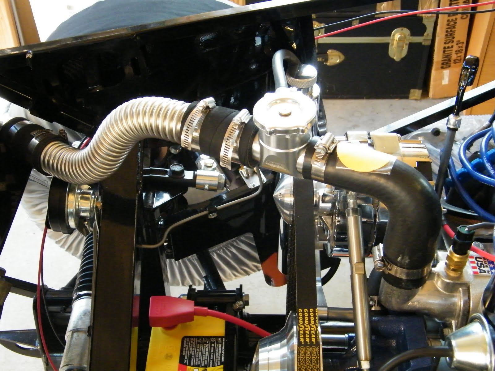
Step 3 remove radiator cap so that the coolant system could be “burped”
At this point the excitement is intense, and as you can see from the video the engine actually started on the first attempt and initial gauges checks all looked good.
At 190 degrees the thermostat opened, this quickly leveled the engine temperature at 184 degrees for the rest of the initial testing. Note: the water temperature gauge supplied is in degrees Celsius, 184F is approximately 82C.
Oil pressure at 850 RPM was a constant 55psi dropping to 40psi at higher RPM’s, the voltage remained at a steady 14 volts, fuel pressure is set at 43psi.
The engine was run through a heat cycle of approximately 30 minutes. This will be repeated over the next few days to check for leaks created from heat cycles and to continue the EFI adaptive learning process.
Overall a smooth and successful first start, and a great early Christmas present.
Sunday, December 19, 2010
Vapor Canister & Odd’s and End’s – 4 hours
Vapor lines were run from the gas tank breather and rear axle breather into the canister. The purpose of the canister is to filter gasoline and oil odors as the vapor passes through the charcoal filter.
Lastly today the clutch cable supplied from Factory Five was replaced with an original Ford OEM cable, if you recall in an earlier block it was suggested that an original cable needed less leg pressure to operate. I am pleased to confirm that this is the case, for some reason there is no binding or resistance with an original cable.
Saturday, December 18, 2010
Flexible Fuel Hose – 4 Hours
Normally I am not one for gadgets, over the years I have happily ripped up my hands forcing braided hose into a AN fitting, but no more. I came across this great gadget from Koul Tool, the video explains all. After making three complete hoses today I have to say it is as easy to use as the video suggests.
Tip of the day: A great way to cut braided hose is to mount 2 hacksaw blades, one with teeth forward the other with teeth backwards, this cuts in both directions and significantly reduces fraying of the braid.
Sunday, December 5, 2010
FAST EFI Computer – 2 Hours
Exhaust Hanger & Wiper Motor – 3 Hours
With both exhausts parallel to the chassis and ground the exhaust hangers were mounted, these provide additional support to the exhaust pipe, and reduce potential vibration stress fractures at the header.
Friday, November 26, 2010
First Engine Crank – 1 Hour
The original plan was to start the engine at Thanks Giving, unfortunately work has got in the way, really cannot complain, after all its work that pays for this car.
With the engine and dash wiring complete it was time to crank the engine over, first the clutch neutral tested for functionality and the area around the engine bay was checked for loose wires and other debris. As you can see from the video, the test went to plan.
The new engine start date is December 23rd, a fitting date as this will be 1 year since the car was delivered. This leaves plenty of time to mount the FAST EFI computer, hook up the fuel line, and add a charcoal filter.
Please enjoy the video, it made my Thanks Giving.
Dashboard Wiring – 5 Hours
Tried to stick with 3 main cable runs, the upper cable run consists of the gauge feed and illumination pigtails, the cable run below the 2 lower gauges is for the horn, turn and main beam dash lights, this left room for the dash harness to run at the bottom of the dashboard.
Sunday, November 21, 2010
It’s the small stuff that takes the time – 10 Hours
With the panels back from the powder coater the dash filler was permanently installed, along with the fuse panel support and the passenger foot box filler pieces.
The inertia switch was mounted to the left of the filler panel; beading was run around the dash filler to stop cable fraying.
Moving to the engine bay the O2 sensor connector was mounted to the chassis, the positive battery cable was run to the disconnect switch. The one wire alternator cable was also run to the same side of the disconnect switch via a mega fuse.
You may have noticed that all the wiring is specific to first engine start, over the next few days all engine wire will be completed (coil, starter), along with dash gauges, and ignition switch. Current plan is to at least crank the engine at Thanks Giving, with first engine start set for December 23rd, one year since the kit first arrived!
Saturday, November 13, 2010
Final Installation of Radiator – 4 Hours
Factory Five provide a length of corrugated stainless steel hose which requires cutting to length, and formed to fit. The upper hose needed bending into a simple S shape to accommodate the vertical displacement between the radiator and the billet coolant filler.
Passenger Side Header, Exhaust and O2 Sensor – 2 Hours
As with the driver’s side, the header was mounted using Stage 8 bolts and fasteners. When the exhaust was mounted and checked for parallelism to the frame and horizontal to the floor it was found that the passenger exhaust flares outwards by 1” over the length of the exhaust.
Sunday, November 7, 2010
Which wire goes were! – 4 Hours
All quality automotive vehicles have the negative connected directly to the engine, a ground cable is then run to the chassis (see October 10th post – Headers and Exhaust).
A positive cable was run from the battery post to the battery cut off switch, a 10 gauge wire was run from the alternator to a Mega fuse and then to the same terminal of the battery cut off switch. A single cable will then be run from the other side of the battery cut off switch to the large solenoid post.
Parking / Emergency Brake – 1 Hour
Some of alterations were required, a small tab on the TKO600 gearbox was cut off to clear the linkage mechanism, and similarly the mounting bracket required slight surgery to clear the ratchet. Finally the tab which operates the parking brake indicator light required filing to clear the mounting braked at full stroke.
Note: Do not pull the horse shoe pin until you have mounted the parking brake for the last time as this releases the automatic adjuster to take up slack in the system. The standard Mk3.1 emergency brake cables supplied are for a drum brake setup and so as you can see from the picture reach past the T bar. At build school the recommendation was to purchase two 94 or later cables (left / drivers) side is shorter and typically cheaper.
Sunday, October 31, 2010
Installed Brake Reservoirs & Bleed Brake Lines – 5 Hours
The final decision was to mount the reservoirs centrally on the firewall, on checking the height of the master cylinders I was surprised of how low I was able to mount the cylinders and still keep the reservoir bodies the highest point of the system. (Replenishment brake fluid is gravity fed into the system)
Only 2 small leaks were found in the system, both being at the “T” joints (3 connections) which divert brake fluid to the driver and passenger side calipers. These were tightened up and the brake system bled of air.
DOT5 synthetic brake fluid was used, although there are those who scorn this type of fluid, the fact that it does not function as paint stripper if spilled, easily out ways any slight down side.
Monday, October 25, 2010
Odds & Ends – 5 Hours
Time fly’s when you are having fun, or so it would appear having spent most of the day in the garage with little to show for the effort, however there are point’s of note:
1. The 4 drive shaft bolts tightened to a torque setting of 83 ft lbs, this being the value directly from the Ford Mustang factory manual. This did however require a trip to Lowes to purchase a 12mm 12 point 3/8” drive long reach socket. Having a collection of 12mm 12 point ½” drive sockets the diameter of these sockets are too large to clear the universal joint
2. Thinking ahead, knowing that once the radiator is finally mounted it will be difficult to drill holes in the X member, and after checking a number of possible locations, decided to mount the two tone horns on the front of the X member. This location is personal choice.
3. Installed the clutch cable. At build school the instructors stated that the standard cable supplied in the kit requires herculean strength to operate the clutch, these comments are often iterated on the forum. I am pleased to confirm, neither sources were exaggerated. This will be replaced with an original Ford clutch cable which supposedly rectifies the situation. (Will update post at a later date)
A convenient bolt hole on the front of the cylinder head was the ideal location to mount the clutch cable bracket which keeps the cable away from the exhaust headers.
1. The 4 drive shaft bolts tightened to a torque setting of 83 ft lbs, this being the value directly from the Ford Mustang factory manual. This did however require a trip to Lowes to purchase a 12mm 12 point 3/8” drive long reach socket. Having a collection of 12mm 12 point ½” drive sockets the diameter of these sockets are too large to clear the universal joint
A convenient bolt hole on the front of the cylinder head was the ideal location to mount the clutch cable bracket which keeps the cable away from the exhaust headers.
Sunday, October 10, 2010
Dashboard – 3 Hours
From left to right: tachometer, left turn indicator, main beam, right turn indicator, speedometer.
Top row: Water temperature, oil pressure, voltage.
Middle row: Wiper switch, fuel gauge, clock, main beam.
Bottom row: Horn, ignition, turn switch, lights, hazard, and fan switch
Still undetermined on installing a glove box, due to the limited area behind the dash once the EFI computer is installed.
Installed oil pressure sensor on the engine and ran cabling back to the dash.
Header and Exhaust – 3 Hours
With the header installed the exhaust pipe was bolted in place, although the exhaust pipe is self supporting the vibration hanger still requires installation.
Here’s hoping the same can be said when the passenger exhaust pipe is installed.
Subscribe to:
Posts (Atom)