 Completed drive train installation and alignment, basically this consisted of manufacturing a ¾” spacer to go between the transmission mount and the transmission support. This spacer is only required when installing either a TKO 500 or 600 transmission. The use of the spacer results in the transmission output to be parallel with the ground.
All engine mounting hardware was tightened using the following torque settings:
Engine mount to engine block 50 ft.lb’s
Engine mount to frame 90 ft.lb’s
Transmission mount to transmission support 55 ft.lb’s
 Before installing the drive shaft, the pinion angle requires setting. The ideal pinion angle is when the angle of an imaginary center line from the transmission output and an imaginary center line from the differential input are parallel when under load. This angle can be zero, positive or a negative angle, but must be parallel for the universal joints to function correct. An incorrect pinion angle induces premature wear and “knocking” under load.
 See pinion angle example (this assumes a 1 degree offset).
For the angles to be correct a differential offset angle needs to be accounted for when setting the alignment to compensate for rotational twist which occurs in the differential under acceleration. Basically the input flange of the transmission kicks upwards under load as the transmission tries to rotate around the axle. With a 3 link suspension 1.5 to 2 degrees is recommended.
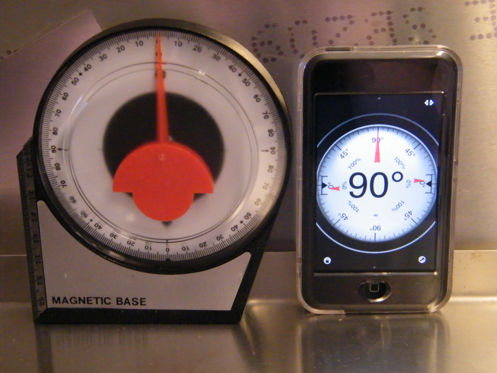 As complicated as it sounds setting a pinion angle is simple, first you will need an angle finder, these can be purchased from any hardware store, of if you have an iPhone or iPod, down load any one of the applications. Make sure the vehicle is on the ground with suspension under load.
 Measure the angle of the transmission output, the easiest way is to place the angle finder on the gasket, in my case this was 0 degrees, next set the differential input adjusting for the offset, in my case -2 degrees (differential input flange pointing towards the ground), the angle is measure from the flange face and adjusted by lengthening or shortening the upper link.
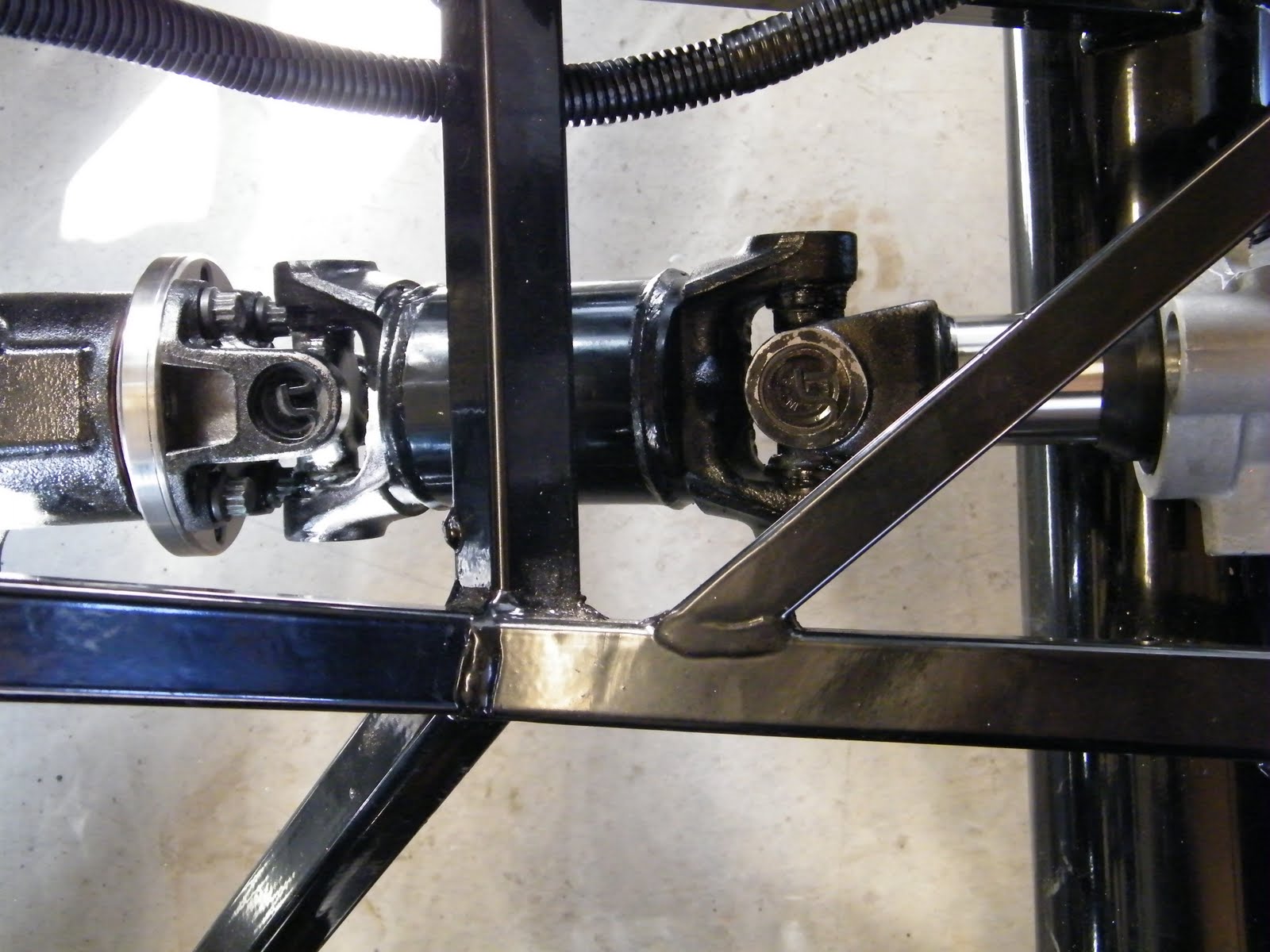 Once set the drive shaft was slid into the transmission and bolted to the differential flange using 4 bolts. Make sure there is no binding by rotating the assembly.

Looking good!
ReplyDeleteHello - I am also building one of these FFR roadsters - and I would submit that there is another concern to be watched - and that is the U-joints in the driveshaft should only be subjected to a maximum recommended angle of 3.5 degrees deflection. In your picture #4 it would appear that that angle has been exceeded. In my case I had to lower the tranny tailstock so that the driveshaft was pointing slightly downwards towards the differential at rest -and accounting for the 2 degree upwards rotation of the differential under load would then be slightly higher on the differential end and pointing down towards the tranny. In either case the maximum 3.5 degree U-joint deflection would not be exceeded.
ReplyDelete